This research complements the large national and international research program, based on wire array Z-pinches, by conducting an in-depth investigation of radial foil geometries. By changing the type of material and the geometry of the experimental setup, it is possible to vary the different parameters governing the dynamics of high energy density plasmas in thin radial foil configurations. We are investigating how plasma dynamics (radiation, magnetically threaded flows and shocks) changes with foil material and electrode geometry. Particular attention is given to the measurement of magnetic fields and plasma velocity fields. The information collected can be used to maximize radiation yield, to understand the physics of magnetically threaded astrophysical jets, to mitigate magneto-hydrodynamics instabilities and to validate the theoretical models used in computational codes.
While foils have been extensively used in cylindrical geometries, thermal and striation instabilities were found very strong and the overall foil mass too large to be optimally driven by actual pulsed-power generators. Historically, replacing cylindrical foils by a series of vertical wires was more successful as the Rayleigh-Taylor (RT) instability subsided. Another major disadvantage of cylindrical foil configurations comes from striation, as the current does not only travel along the vertical direction but also azimuthally. As a result, current channels can twist and deviate from a vertical path, degrading the quality of the implosion and reducing the radiation yield.
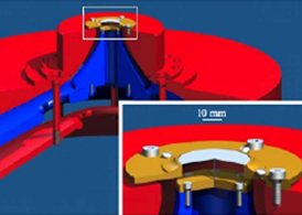
On the other hand, radial foil arrays have two major advantages. First the current is forced to run towards the axis. Hence the current density becomes very large at the center of the foil. Consequently, moderate generators can explode radial foils since the mass density of the foil is not as limiting a parameter as in cylindrical geometries. The other important characteristic comes from the radial geometry. Since the current path is radial, any twisted current channel at the edge of the foil has to straighten to go through the inner (axial) electrode. This phenomenon is extremely important since it favors current symmetry. Despite such advantages, radial foil physics is still largely unexplored.The experimental setup is described in the illustrations on this page.


Above: A laser shadowgraph taken 65 ns after the start of the current rise shows the actual setup with then cathode at the bottom of the image. The large horizontal dark band in the bottom half of the picture is the shadow of the foil holder. The foil is located above. Foil lift, surface plasma and miniature Bdot probes are clearly visible.