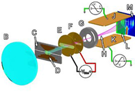
Two streak cameras are available on COBRA. One is a Hamamatsu visible-light streak camera and the other is a Kentech x-ray streak camera. Both work fundamentally the same—i.e., they both “streak” a single dimension of incident photon intensity as a continuous function of time. This single dimension can, for example, be either a spatial dimension (as in a dynamics study) or a wavelength dimension (as in a spectroscopic study). Photons from the single dimension chosen must be incident on the entrance slit of the given streak camera. In the case of the visible light streak camera, the photons are imaged onto the entrance slit and this image is then transferred by the camera’s internal relay optics to a photocathode. In the case of the x-ray streak camera, the x-rays are transmitted directly to the photocathode (without imaging) through a cross slit. For both cameras, the photons reaching the photocathode are converted to electrons via the photoelectric effect. These electrons are accelerated longitudinally within the streak camera by a biases grid. At the end of this longitudinal acceleration, the electrons are focused by an electrostatic lens.
After the electrons have been accelerated longitudinally and focused, they are deflected laterally by a time-varying transverse electric field. This field is created by discharging a bias potential across two plates (one plate on each side of the electron stream). This effectively paints the electron stream onto the phosphor screen in a single sweeping motion (similar to a cathode-ray tube television). The phosphorescence from the phosphor screen is then recorded by film or a digital CCD camera, or it is further intensified by use of a micro-channel plate (MCP). The visible streak system on COBRA, for example, uses an MCP to intensify the streak camera’s phosphor image, and then digitally records the luminescence from the MCP’s phosphor screen via a CCD camera. The digital image is then easily viewable with varying contrast using Hamamatsu’s pre-packaged image software, as well as easily saved for post-processing.
The transverse bias voltage versus time waveform in a streak camera is a non-linear “S” curve. Thus one only uses the approximately linear region in the middle of this curve as the streak time window so that there is a linear relationship between a position in an image and the time of that position. Also, varying streak speeds and time windows can be obtained by making adjustments to this discharge waveform (this is automated for the visible streak camera by the Hamamatsu software, but must be done manually for the x-ray streak camera). The time resolution of a streak image depends on the streak speed, the input slit width, and the streak camera’s internal magnification. For example, if an instantaneous flash of light occurs during a streak, then an image of the input slit will be produced at that particular moment in time. This flashed slit image will then take up some finite fraction of the total streak image in the time direction (based on the slit width and the internal magnification within the streak camera). In other words, if the streak window is 100 ns, and a flashed slit image takes up 5% of the total streak image in the time direction, then the time resolution is 5 ns.
It should also be mentioned that the visible light streak camera can be put into “live mode” (also known as “focus mode”), which allows an experimenter the ability to make optical alignment and focusing adjustments to their system while continually monitoring the effects of those adjustments. Live mode is a system state where the streak camera has no transverse bias potential applied. Thus the electrons stream straight through to the phosphor screen, producing a stationary image of the streak camera input slit (i.e., with a small slit width, live mode will result in a thin horizontal line across the middle of the image). To allow the nearly real-time adjustment-monitoring capability, the system’s CCD camera continually takes pictures and sends them to the system’s PC. The PC then continually updates the image on the computer monitor with the most current one taken by the CCD camera (the image is usually updated every half second or so). Also, by opening the slit wide (i.e., on the order of millimeters), 2D imaging can be accomplished in live mode, which helps when trying to focus an image onto the input slit/plane of the streak camera as well as when trying to align a particular part of an object’s image onto the input slit.
Graphic of a generic visible light streak system illustrating the working principles. The components are:
A. Wire-array z-pinch load (Usually the self emission from the wire plasma is the source of visible light.)
B. Optical relay lens (This could be a system of relay optics.)
C. Streak camera entrance slit
D. Image of wire-array and load region at the entrance slit
E. Electron0emitting photocathode
F. Electron-accelerating grid
G. Electrostatic lens
H. Electron trajectories
J. Upper sweep bias plate
K. Lower sweep bias plate
L. Phosphor screen
M. Detector (film, CCD camera, etc.)
Figure courtesy of J. D. Douglass
